Final MidI Instrument by Maya Pruitt

Solfege Gesture MIDI

CODE

Since last week, I added a flex sensor. This allowed me to map more specific data to each gesture. I also added MIDI code so that notes could be sent over serial to Garage Band. It is still quite finicky, but I had enough resolution to play a simple scale and even notes in different orders.

#include <Arduino_LSM6DS3.h>
#include <MIDIUSB.h>

#define FLEXPORT 14
#define ALPHA 0.5
float roll, pitch, ax, ay, az;
float fx, fy, fz;
int flexed;

byte Do = 60;
byte Re = 62;
byte Mi = 64;
byte Fa = 65;
byte So = 67;
byte La = 69;
byte Ti = 71;

byte prevNote;

void setup() {
 //begin receiving IMU data
 Serial.begin(9600);
  IMU.begin();
}

void loop() {
  flexed = map(analogRead(FLEXPORT), 750, 930, 0, 100);
  //Serial.println(flexed);
    //read IMU data
  IMU.readAcceleration(ax, ay, az);
  //Convert to sensor fusion values
  fx = ax * ALPHA + (fx * (1.0 - ALPHA));
  fy = ay * ALPHA + (fy * (1.0 - ALPHA));
  fz = az * ALPHA + (fz * (1.0 - ALPHA));
  
  //equations for roll & pitch
  roll = (atan2(-fy, fz)*180.0)/M_PI;
  pitch = (atan2(fx, sqrt(fy*fy + fz*fz))*180.0)/M_PI;
  midiEventPacket_t sound;
  byte note = 0;
  byte cmd = 0x90;
  Serial.print("PITCH: ");
  Serial.print(pitch);
  Serial.print(" | ROLL: ");
  Serial.print(roll);
  Serial.print(" | FLEXED: ");
  Serial.print(flexed);
  Serial.print(" | ");

  //map pitch & roll data to solfege notes
  if(abs(roll) <= 10 && abs(pitch) <= 10 && flexed > 75){
    //Do, MIDI 72
    note = Do;
    Serial.println("Do");
  }

  if(abs(roll) >= 0 && abs(roll)<= 10 && pitch <= -15 && pitch >= -45 && flexed < 10){
    //Re, MIDI 74
    note = Re;
    Serial.println("Re");
  }

  if(abs(roll) <= 10 && abs(pitch) <= 10 && flexed < 10){
    //Mi, MIDI 76
    note = Mi;
    Serial.println("Mi");
  }

  if(roll >= -65 && roll <= -45 && pitch <= 3 && pitch >= -25 && flexed > 75){
    //Fa, MIDI 77
    note = Fa;
    Serial.println("Fa");
  }

  if(roll >= 55 && roll <= 65 && pitch <= 0 && pitch >= -10 && flexed < 10){
  //So, MIDI 79
  note = So;
   Serial.println("So");
  }

  if(abs(roll) <= 10 && abs(pitch) <= 10 && flexed > 20 && flexed < 70){
    //La, MIDI 81
    note = La;
    Serial.println("La");
  }

    if(abs(roll) >= 0 && abs(roll)<= 17 && pitch <= -35 && pitch >= -40 && flexed > 40){
    //Re, MIDI 74
    note = Ti;
    Serial.println("Ti");
  }

  if(!note){
    cmd = 0x80;
    note = 0x00;
  }
  if(note != prevNote){
   sound = {cmd >> 4, cmd | 0, note, 0x45};
   MidiUSB.sendMIDI(sound);
   delay(100);
  }
  if(note){
    prevNote = note;
  }
Serial.println();
}

FABRICATION

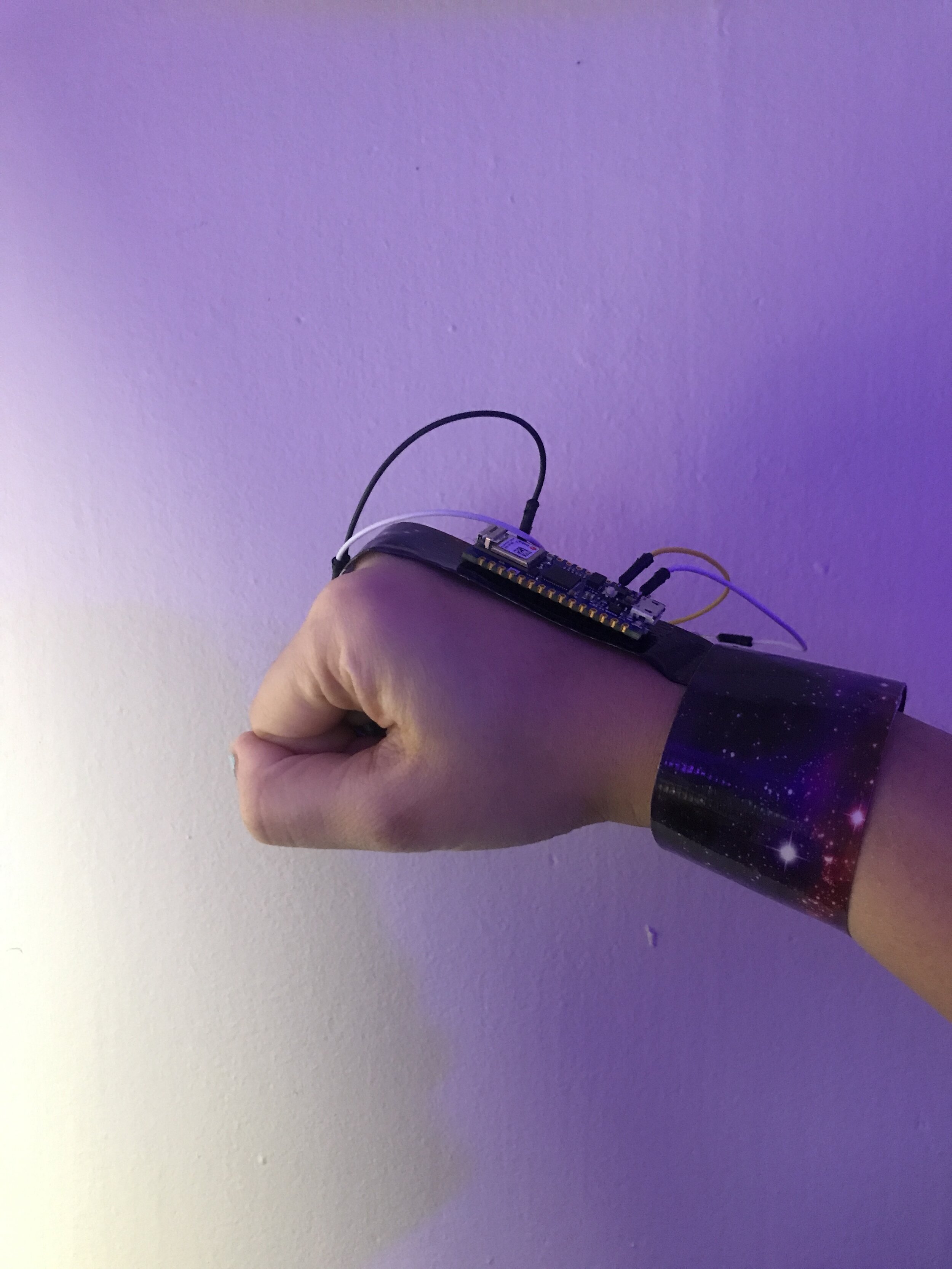
This was the ultimate at-home fab job. I used duct tape (of a galaxy variety) and velcro. It’s not the prettiest thing to look at but it does kinda feel bionic and the duct tape is surprisingly comfortable.

DEMO

Mapping IMU to Gestures by Maya Pruitt

Made a little progress:

I wanted to try mapping IMU values to the hand symbols. Instead of mapping the raw data, I was advised by my partner, who works with drones, to convert the IMU data to pitch, roll, and yaw or angles of change in position/rotation. A few equations found here allow for this sensor fusion. This made the IMU values more reliable and easy to read.

For a quick hacky fab start, I attached the Arduino to the top of my hand with a hair tie to test.

I performed the gestures and assigned ranges of pitch & roll values to correspond with each gesture. (i.e. if pitch is between these values, and roll between these, then that’s note “do”….maybe there is a better way to do this?) I can only get to “So” with IMU alone, so with the combination of flex sensors, I think it’ll become more precise.

Here is a quick gif of the initial mapping.

IMUmapping.gif

I notice that when changing hand gestures, it’ll pass through notes I may not want to play. Not sure how to avoid this.

MIDI Instrument Ideation & Early Testing by Maya Pruitt

BACKGROUND

This semester, I joined the NYU Women's choir. With no formal music training, its been really fun learning more about sight singing and music notation. One of the most interesting aspects is that Solfege notes have a gestural visualization. Our choir director often has us simultaneously make these hand symbols while we sing. I liked the idea of having these gestures make sound directly. Like singing itself, you become your instrument.

e881b75db596114fba2f601df81b55ca.jpg

BOM

Screen Shot 2020-04-15 at 9.37.49 AM.png

I’ve purchased a few different sensors, because I don’t want to settle on anything just yet. I enjoy trying different sensors and want to experiment with their different inputs. However, I think nearly all of the gestures can be created with IMU input.

IMU TEST

Below is a video of converting IMU values to frequency to play different notes depending on angle/position of the Arduino Nano.

Reference: https://pypi.org/project/pysine/

QUESTIONS

In real life, holding ‘do’ at different heights represents an octave shift. The symbols are also universal because you can change key vocally.

How can these musical aspects be expressed in instrument form? Button to change octave/key? Acceleration?

Flashlight – Human Interface Device by Maya Pruitt

CONCEPT: Melding the physical and digital worlds with tangible interaction

Our concept for this project was to recreate a physical flashlight that instead creates light in a virtual scene. This acts as a USB HID device by controlling the mouse on a computer screen.

PROGRAMMING PROCESS

Git repo here.

Moving the mouse

Using the Mouse library and the Arduino Nano 33 iot’s built-in accelerometer, Dylan wrote a program to reads the gyroscope values of the board and move the computer mouse accordingly.

void readGyro() {  
    float x, y, z;   
    if (IMU.gyroscopeAvailable()) {    
        IMU.readGyroscope(x, y, z);     //recalibrate incoming data;    
        int x_avg = round(x) + offset_gx;    
        int y_avg = round(y) + offset_gy;    
        int z_avg = round(z) + offset_gz;     
    if (hasMouseBegun) {     
        moveMouse(x_avg, y_avg, z_avg);    
        }  
   }
} 


Bluetooth

Since flashlights are usually battery operated and incredibly portable, it felt important to try to mimic this ability. To make the flashlight untethered, we decided to use bluetooth (Bluetooth BLE library). I focused my efforts on this, programming the Arduino inside the flashlight to act as a peripheral (powered by battery) that connects to a second central Arduino that plugs into the computer via USB. Video of it the peripheral sending gyroscope data to the central below:

COVID

With changes brought by Coronavirus, Dylan and I truly had to divide and conquer to make this work. I handed the Arduinos back to Dylan, so that he could work on the “fabrication”.

DEVICE DESIGN

BOM here.

Fortunately, we were very intentional about our device design deliberately maintaining the intuitive nature of a flashlight. We chose to use an existing flashlight enclosure and didn’t have to make anything new. Dylan worked on rewiring the switch, changing the light to a neopixel, and connecting the battery.

IMG_2190.jpg

He also added more functionalities like LEDs to flash it is in pairing mode and change to statically lit when it’s connected. This is a feature that we felt would make it feel familiar as a bluetooth device.

Central

Central

Peripheral

Peripheral

UNITY SCENE

Dylan created a dark forest scene in Unity and handed that off to me finalize. We felt this is a setting that would work well with the flashlight devices. To create magic, I’m adding elements that will react to the light.

HID_room_unity_inprogress.jpg

Clock Controls by Maya Pruitt

ASSIGNMENT

Make the controls for a desk or bedside clock or timer.  At minimum this should include controls to set the hour and minute.

CODING PROCESS

I started by selecting a few components that I had on hand, so I would be able to dive in right away. I used a 16-2 LCD screen, push buttons, a potentiometer, and my Arduino Uno. I set up my bread board with the guide of a project I found online. This set up the clock setting controls with a separate button for hours and minutes. However, I quickly decided that I wanted to simplify my controls to just 2 inputs: one to change the state and one to set the time. I wanted to use a push button to change the mode and a potentiometer to set the time. These two actions felt distinct and intuitive enough (and I hoped would simplify the code). Though we reviewed rotary encoders in class, I was instinctually drawn to using a potentiometer instead because of its smoother feel. I also felt that the 180 degree rotation emulates the idea of the sun rising and setting.

Testing time setting. Button pushes change the mode, cycling through hour change and minute change, until the final “display-only” state where it locks it in and the potentiometer won’t have an effect.

Testing time setting. Button pushes change the mode, cycling through hour change and minute change, until the final “display-only” state where it locks it in and the potentiometer won’t have an effect.

DEVICE DESIGN

Originally I wanted to try using two panels with standoffs as we learned in class, but I ended up finding a basket that felt like a good clock size. It felt like it would feel more like a “device” if it were truly enclosed.

In Vectorworks I drafted the front panel. In version 1, I experimented with the placement of the buttons. Bottom-right felt most natural though probably a bit biased towards right-handedness. Putting the buttons above the screen was an attempt to make it feel like a little robot, serving as eyes. However, with the button and knob that I had in mind, it felt unbalanced. The knob extends too far out from the panel in comparison to the button and that didn’t work well sitting above the screen.

og_vectorworks.png

For my first couple rounds of laser cutting cardboard, the sizing of my panel was COMPLETELY off. I soon realized that I was entering the width and height dimensions in the wrong boxes in Vectorworks, so I was affecting the position of the shape on the grid but not its size. Tragic.

sizing_mistake.png

Since my intention was to create a desk clock, the way the basket would sit upright was very important to its look and feel. The basket would be turned on its side but didn’t make for a readable angle. If I pitched it back it felt much more natural to look at. In the final design, I created feet that change the angle of the basket. They slip onto the side edge of the basket and the front panel slips onto the feet.

Left:: Panel design, Right: Angled feet.

Left:: Panel design, Right: Angled feet.

If I could redo the design, I would consider weight choices more carefully. Since the materials are so light, pushing the button can only work if the clock is laid down on its back or if you use your other hand to hold it in place.

unweighted_problem.gif

FINAL TOUCHES

With the final cardboard iteration in place, I was ready to create the panel in acrylic. I also returned to the code to incorporate the extra feature. Unfortunately, the laser cutters were inoperable in the final hours I had to work on the project, so I had to use my cardboard version instead. Time got away from me and I wasn’t able to add a more interesting clock feature, so I used the same logic of mode changing and setting to also add the date.

front.jpg
above.jpg


40x by Maya Pruitt

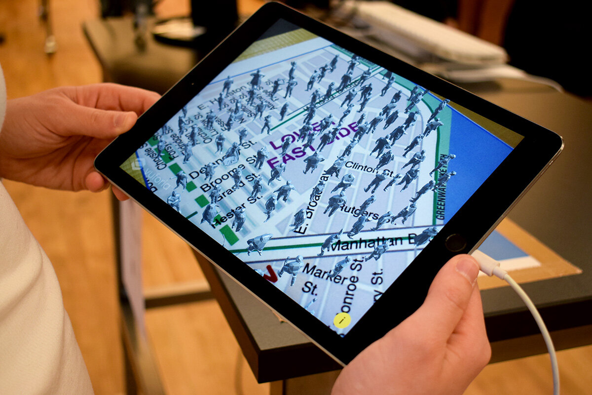
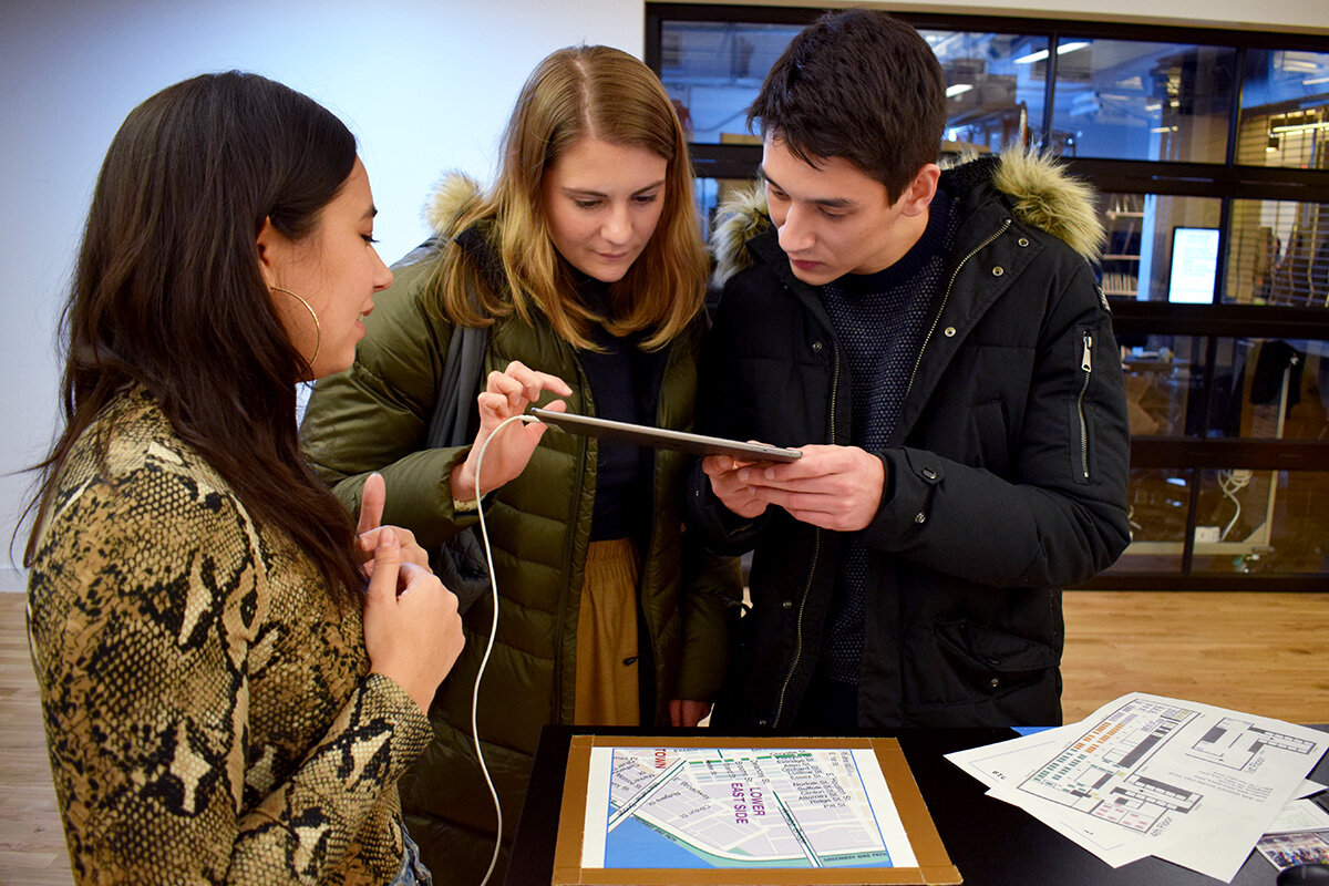
What? 40x (pronounced “Forty Times”) is an augmented reality data art piece that illustrates the lack of affordable housing in the Lower East Side. In NYC, property management companies require renters to have an annual income of 40 times their monthly rent. In certain areas the disparity of rent prices to median household income is incredibly stark, very much so in LES. In this experience, users see 100 figures appear representing the total population of the Lower East Side. Over time the figures disappear leaving a remaining 8% of people to represent those who can actually afford to live in their neighborhood based on the 40x rule. Users can toggle for more information and statistics regarding the data used in this project by touching the screen.

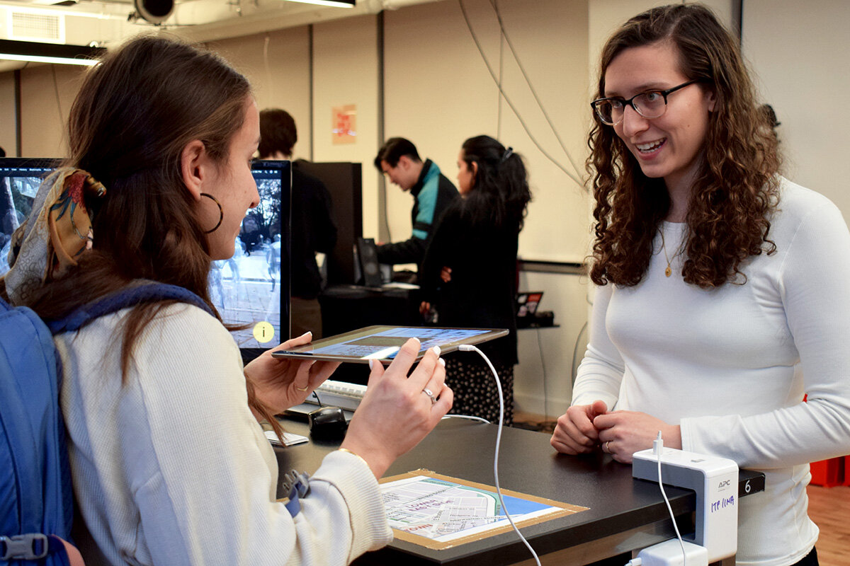
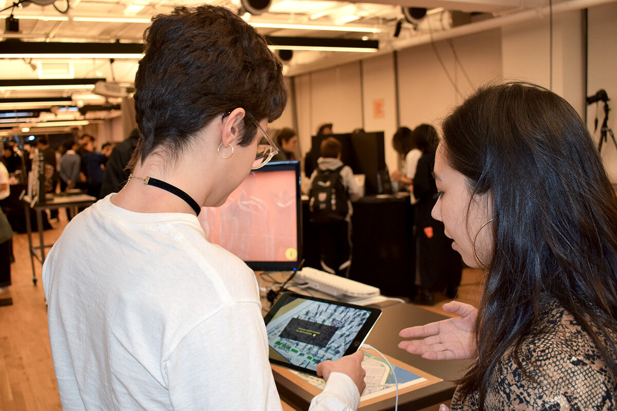
How? This AR experience was designed in Unity and presented in two forms. The first, showcased in the video, acts as an intervention into public space. The mobile device searches for a ground plane so that figures may appear life size on location in the Lower East Side. The second form was a table top demonstration designed for ITP’s public exhibition, the Winter Show 2019. In this version, an image of a LES map spawns the figures.

Why? As New York evolves it is becoming progressively more unaffordable, affecting low income populations the most. With such a large of percentage of rent-burdened New Yorkers, meaning that households spend 30% or more of their incomes on rent, 40x serves to bring light to this issue and start a conversation.

The experience incorporates technical applications of Vuforia, ground plane tracking, image tracking, animation, and UI in Unity.

Created in collaboration with Caroline Neel.

See more about the research and design process:

40x at the ITP Winter Show:

I N T R A T E R R E S T R I A L by Maya Pruitt

INTRATERRESTRIAL is an AR narrative experience about extraterrestrial communication that interweaves interactive augmented reality with cinematic story telling.

How? This AR experience was designed using Vuforia and ARKit in Unity. Users become the main character of the story and are initially guided through video with subtitles to act as their inner thoughts. Once the supporting character of HQ is introduced, instructions to find the next AR components are provided through her voice and UI elements on screen of the user’s device. The mechanics work like a scavenger hunt, inviting the user to explore their realities to progress through the story.

Why? This project seeks to push the boundaries of Augmented Reality not only in content but also in its purpose. Each AR segment of the story is designed to create a more seamless augmentation. Rather than having objects randomly appear in the user’s physical space, Intraterestrial seeks to change it before the user’s eyes. In addition, the AR serve as crucial plot points to drive the over arching story. While it embodies characteristics of the more passive experiences of video games or film, its ultimate goal is to combine the digital and physical realms to encourage users to actively venture out into New York City. For there may be extraterrestrials among us!

Intraterrestrial incorporates technical applications of Vuforia, ARKit, UI, 3D modeling, animation, texture mapping, image tracking, and ground plane recognition in Unity.

DSC_0052.JPG

Read more about the development process here.

Final Project Progress: Final Video Draft by Maya Pruitt

First draft of the final video. This cut helped me see the main flow of the narrative. The AR components have not been added yet and are depicted with After Effect animations as placeholders. For the final version I am making it a self-requirement to showcase the AR components working with image tracking in real life.

UPDATE: After meeting with Mark he gave me some major notes, and I worked actively to adjust them for the final documentation:
- slowed down the map animation
- made the shatter inward to improve the illusion
- added a visual or audio cue when it switches to HQ on the sci-fi interface
- paned back to the map when HQ asks if you've seen anything strange lately
- got all the AR components working in real life!
- asked a friend and stranger to run away from the UFO to add some drama!