Hard to believe it has already been half of a semester and this was my final project for Intro to Fabrication. It proved to be the most difficult one yet.
The assignment was to mount a motor. Sounds easy, but we hadn’t even learned about operating DC motors yet in Physical Computing, so we were starting a bit in the dark. Obviously, since this is a fabrication course, the focus is on the physical and less on the computing aspect of the project, but a beautifully crafted container seems pointless if its contents don’t work. Thus, I was determined to learn about motors, get one running, and tie it all together with fabrication.
This project really tested me, my time management, and my ability to improvise. It started off pretty rough, feeling like I hit a wall for inspiration. What was I going to make? I took apart a disc printer and other forgotten electronics from the junk shelf and ended up scavenging some motors! But it turned out that what I recovered were stepper motors, which seemed even more difficult to master in the weeks time.
Finally the idea came when thinking about the motor as a way to make a sort of continuous animation. The real life draw() function if you will! Reflecting on the lack of sleep ITPers get, I decided to bring to life the idea of counting sheep to fall asleep. I was especially inspired by automata like this one, that turn circular motion by a crank into different types of kinetics.
Sorry for the long introduction, here’s how I made a sheep jump over a fence.
Step One: Get your motor runnin’
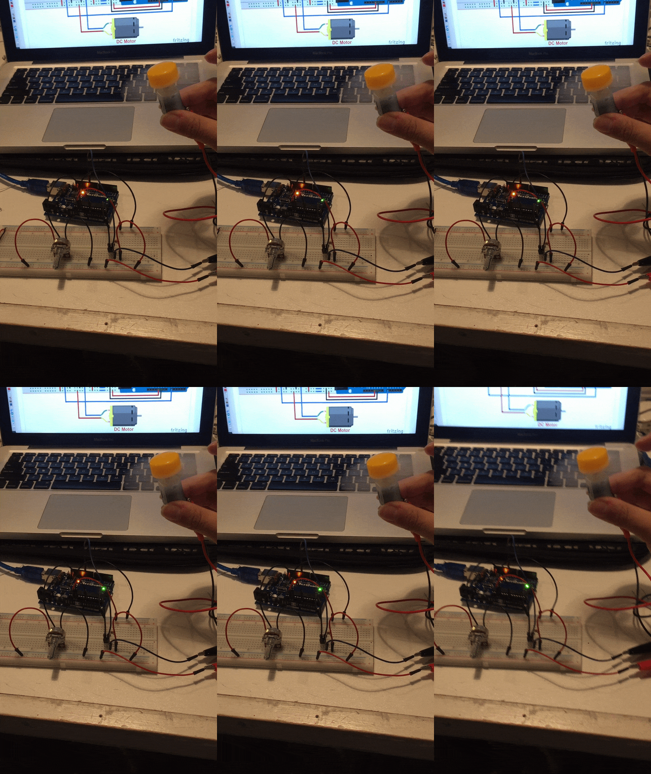
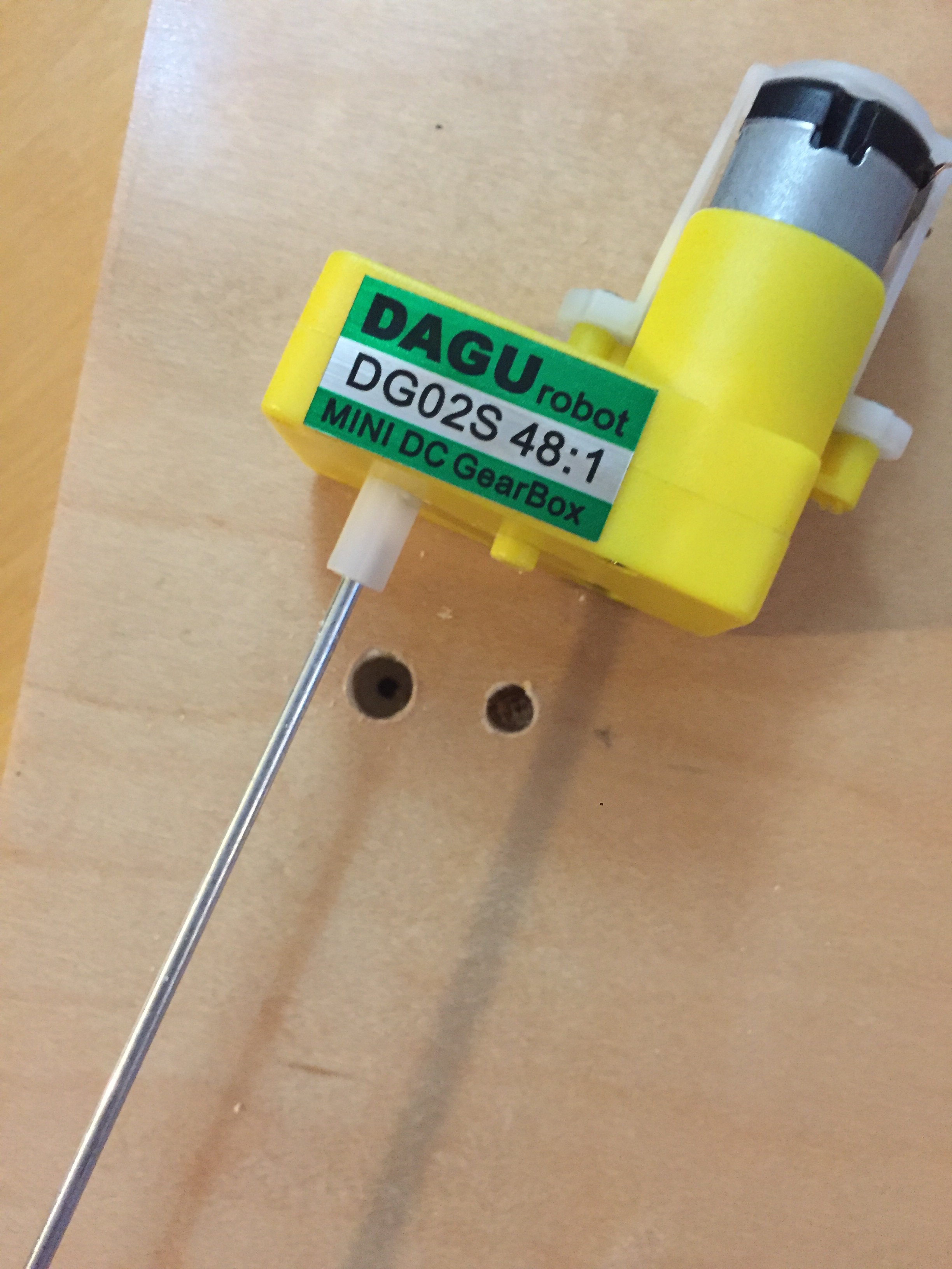
My first step was getting a motor running. Through a bunch of trial and error, an expensive trip to tinkersphere, and consultation with David Rios, I managed to hook up a dc motor to be powered only by an Arduino, and mapped to a potentiometer to control its speed. Upon David’s recommendation, I used a DC motor in a gear box to help slow the motor down. This was not only more suited for the movement I was looking for, but is also easier to mount! Yay, win win.
Step two: prototyping
While I had made some sketches of how I would make my automata, it was hard to envision it until I started prototyping and making some things out of cardboard. During this stage, I figured out what kinds of elements I would need like a sheep, circular panels, and a fence. I drew these elements from scratch in illustrator for future laser cutting. I knew that if I put a disc on an axel attached to the motor it would spin like wheel. If I attached a stick from the disc it would also spin but with a wider radius and this would be what makes it looking like a jumping sheep. However, figuring out how to put it all in one piece was the challenge. I made a janky cardboard prototype to hash things out. I knew I should have two walls to put the axel horizontally between and the the motor could be mounted to the wall. I knew I would need wood if I were to have any stability.
Step 3: Cutting pieces
Luckily I had been stashing good pieces of scrap wood for a later project and had a good amount of material to work with. I figured out that I essentially needed to create a box,it didn’t have to be fully enclosed, but it needed to be tall enough or have enough room below the axel to have the sheep swing through without touching anything.
I laser cut a bunch of pieces, including the top of the “box”. While I prototyped with cardboard, I wanted to use of leftover acrylic for the sheep in order to try some other laser cutting techniques like engraving and the sharpie trick to color it! Acrylic would also be a little heavier which would help to slow down the movement.
Step 4: Assembly
This stage of the process always seems likes its going to be the simplest. You’ve finally figured out your idea, you’ve cut all your pieces, how hard could it be to put it all together? Answer: extremely.
My wood was wonky, I didn’t plan how I would adhere anything, etc. I managed to glue the wood pieces together and screw them for extra support. I drilled holes for the axel rod to go through, the motor shaft, as well as a weird nub on it. This way the gear box would lie flesh to the wall.
In the process of testing my project, I ripped a lead off the motor. ABSOLUTE PANIC. But i figured out how to take a motor apart and replaced the leads for another pair from a different motor. Guess that trip to Tinkersphere wasn’t so bad after all (I bought backup motors for stupid things like this). If you ever destroy those flimsy leads off a motor, I GOTCHU.
With things back under control, I focused on the main aspect of this project, mounting that motor! I had to drill out holes to be bigger to make sure the axel and the plastic nub had more room. Just like my table, I discovered that plumbing supplies are quite useful. My dad had some plumbers strapping lying around (thanks Dad!), which is easily bendable. Voila! A homemade bracket!
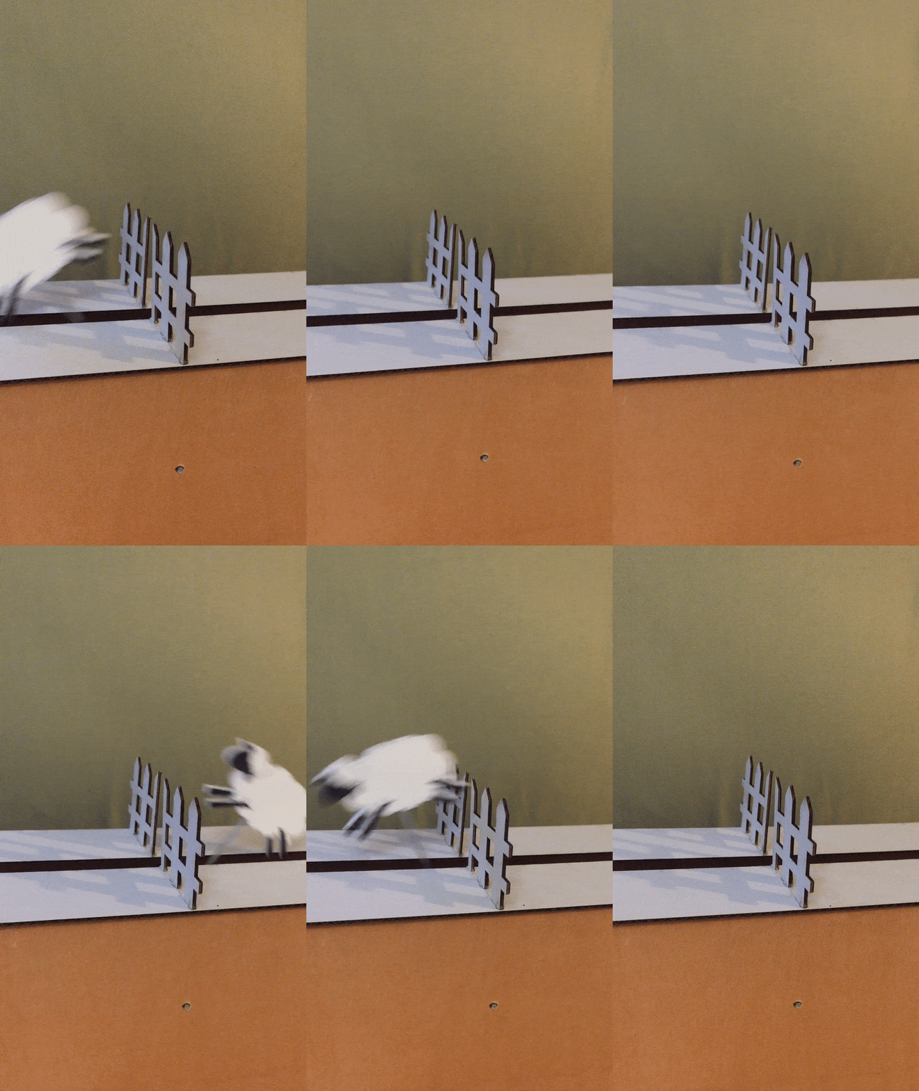
It took a long while to put the wheel and sheep onto the motored rod. It also took a whole lot of hot glue. But with persistence, I got everything running. With some final touches, like adding the fence, the sheep successfully jumps over the fence.
FINAL THOUGHTS:
There is definitely a lot I would do differently for this project. It felt very hap hazard the whole time, and I could have planned things out better. I would also like to make a version where the Arduino and breadboard could be enclosed. However, ultimately, I am quite proud of how it turned out. I combined a lot of skills I have learned throughout the course, and really learned how to improvise and adapt. It’s very exciting to make things work AND look fabulous. Cheers to a great course and hopefully getting my sleep back!
ok, time to count sheep. One, Two…..Zzzzzzz


