Fabrication

WEEK SIX: FAB FINAL! by Maya Pruitt

Hard to believe it has already been half of a semester and this was my final project for Intro to Fabrication. It proved to be the most difficult one yet.

The assignment was to mount a motor. Sounds easy, but we hadn’t even learned about operating DC motors yet in Physical Computing, so we were starting a bit in the dark. Obviously, since this is a fabrication course, the focus is on the physical and less on the computing aspect of the project, but a beautifully crafted container seems pointless if its contents don’t work. Thus, I was determined to learn about motors, get one running, and tie it all together with fabrication.

This project really tested me, my time management, and my ability to improvise. It started off pretty rough, feeling like I hit a wall for inspiration. What was I going to make? I took apart a disc printer and other forgotten electronics from the junk shelf and ended up scavenging some motors! But it turned out that what I recovered were stepper motors, which seemed even more difficult to master in the weeks time.

Finally the idea came when thinking about the motor as a way to make a sort of continuous animation. The real life draw() function if you will! Reflecting on the lack of sleep ITPers get, I decided to bring to life the idea of counting sheep to fall asleep. I was especially inspired by automata like this one, that turn circular motion by a crank into different types of kinetics.

Sorry for the long introduction, here’s how I made a sheep jump over a fence.

Step One: Get your motor runnin’

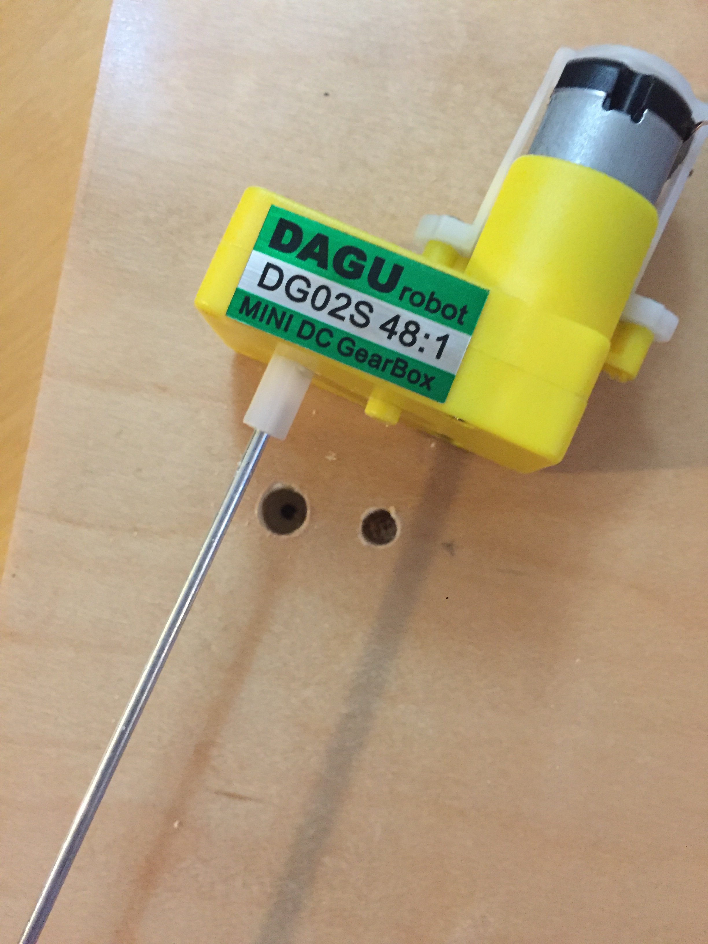
My first step was getting a motor running. Through a bunch of trial and error, an expensive trip to tinkersphere, and consultation with David Rios, I managed to hook up a dc motor to be powered only by an Arduino, and mapped to a potentiometer to control its speed. Upon David’s recommendation, I used a DC motor in a gear box to help slow the motor down. This was not only more suited for the movement I was looking for, but is also easier to mount! Yay, win win.

motor_fan.gif

Step two: prototyping

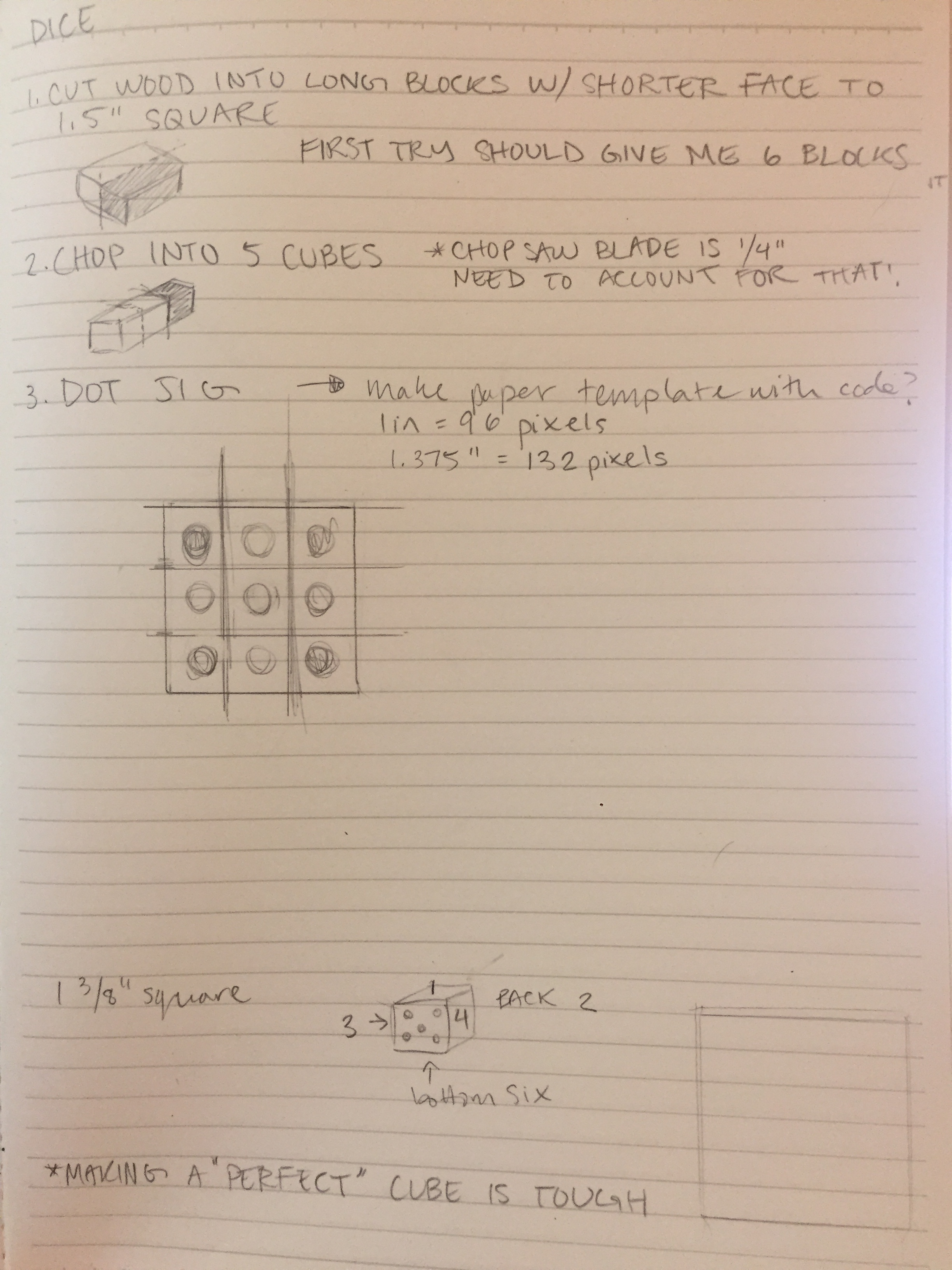
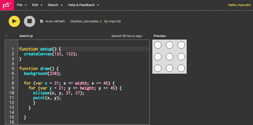
While I had made some sketches of how I would make my automata, it was hard to envision it until I started prototyping and making some things out of cardboard. During this stage, I figured out what kinds of elements I would need like a sheep, circular panels, and a fence. I drew these elements from scratch in illustrator for future laser cutting. I knew that if I put a disc on an axel attached to the motor it would spin like wheel. If I attached a stick from the disc it would also spin but with a wider radius and this would be what makes it looking like a jumping sheep. However, figuring out how to put it all in one piece was the challenge. I made a janky cardboard prototype to hash things out. I knew I should have two walls to put the axel horizontally between and the the motor could be mounted to the wall. I knew I would need wood if I were to have any stability.

IMG_2506.JPG
IMG_2483.JPG

Step 3: Cutting pieces

Luckily I had been stashing good pieces of scrap wood for a later project and had a good amount of material to work with. I figured out that I essentially needed to create a box,it didn’t have to be fully enclosed, but it needed to be tall enough or have enough room below the axel to have the sheep swing through without touching anything.

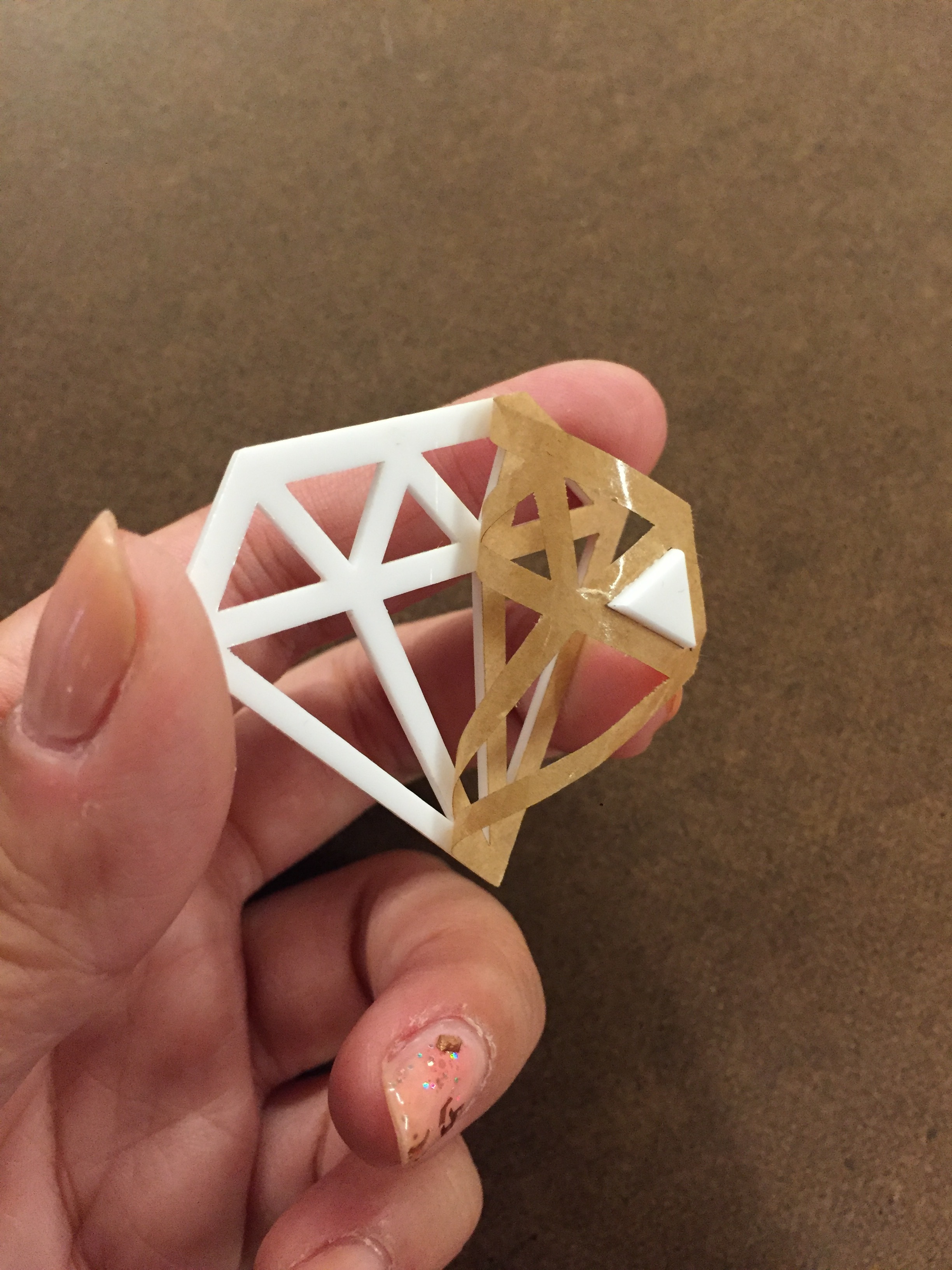
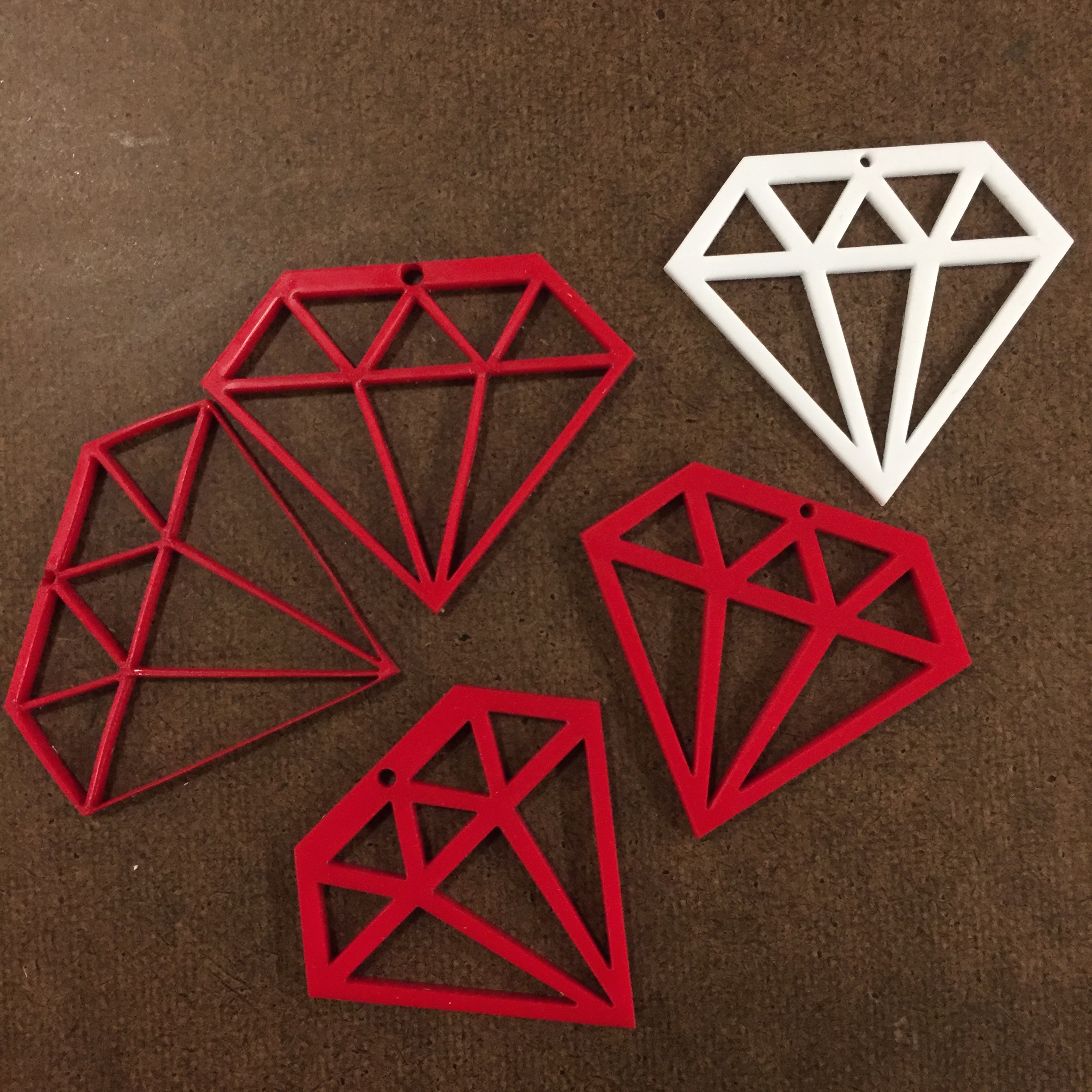
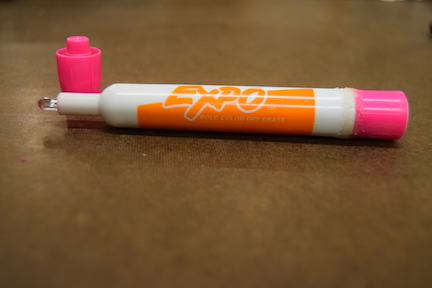
I laser cut a bunch of pieces, including the top of the “box”. While I prototyped with cardboard, I wanted to use of leftover acrylic for the sheep in order to try some other laser cutting techniques like engraving and the sharpie trick to color it! Acrylic would also be a little heavier which would help to slow down the movement.

IMG_2510.JPG
IMG_2509.JPG

Step 4: Assembly

This stage of the process always seems likes its going to be the simplest. You’ve finally figured out your idea, you’ve cut all your pieces, how hard could it be to put it all together? Answer: extremely.

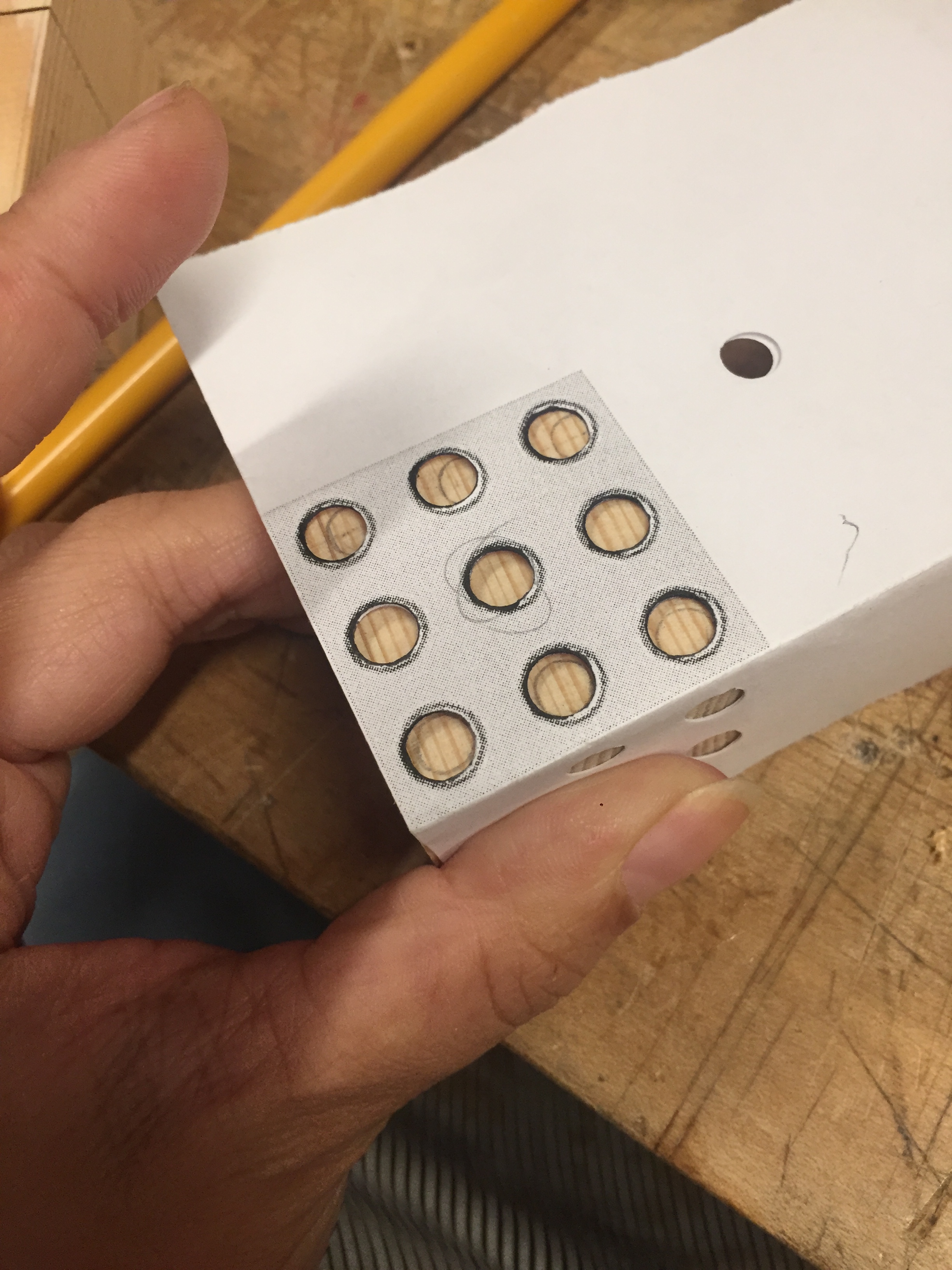
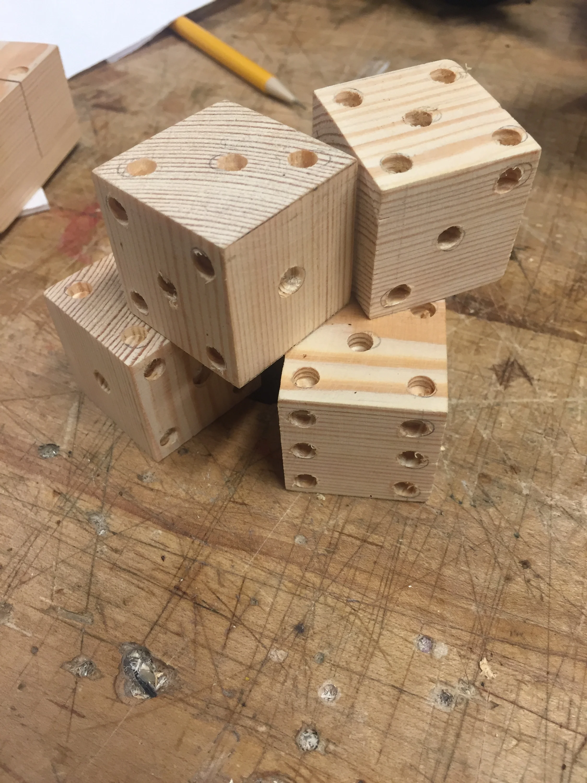
My wood was wonky, I didn’t plan how I would adhere anything, etc. I managed to glue the wood pieces together and screw them for extra support. I drilled holes for the axel rod to go through, the motor shaft, as well as a weird nub on it. This way the gear box would lie flesh to the wall.

IMG_2492.JPG
IMG_2485.JPG
IMG_2488.JPG
IMG_2484.JPG
IMG_2489.JPG
set up to drill.JPG
IMG_2495.JPG

In the process of testing my project, I ripped a lead off the motor. ABSOLUTE PANIC. But i figured out how to take a motor apart and replaced the leads for another pair from a different motor. Guess that trip to Tinkersphere wasn’t so bad after all (I bought backup motors for stupid things like this). If you ever destroy those flimsy leads off a motor, I GOTCHU.

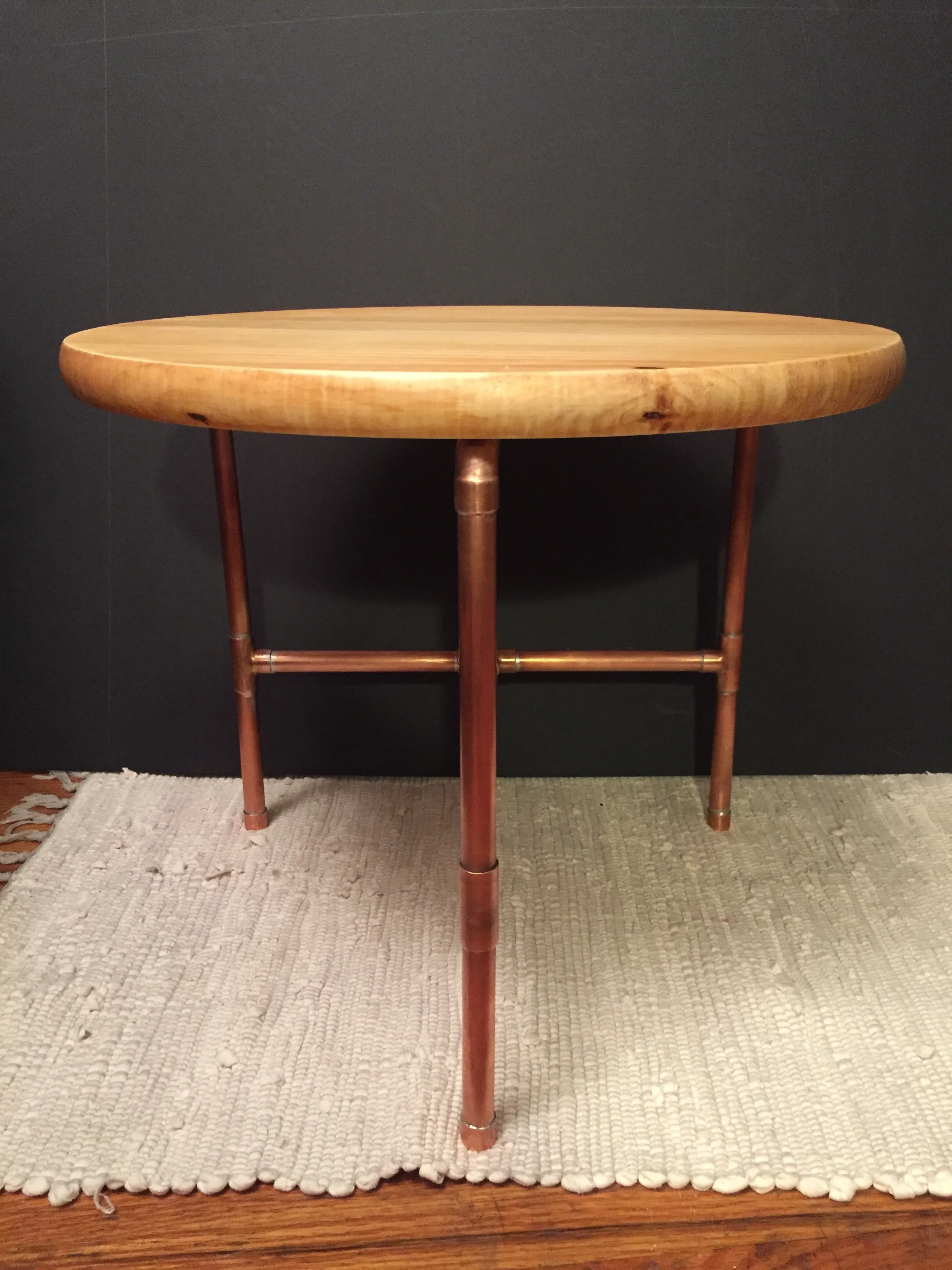
With things back under control, I focused on the main aspect of this project, mounting that motor! I had to drill out holes to be bigger to make sure the axel and the plastic nub had more room. Just like my table, I discovered that plumbing supplies are quite useful. My dad had some plumbers strapping lying around (thanks Dad!), which is easily bendable. Voila! A homemade bracket!

IMG_2493.JPG
IMG_2497.JPG

It took a long while to put the wheel and sheep onto the motored rod. It also took a whole lot of hot glue. But with persistence, I got everything running. With some final touches, like adding the fence, the sheep successfully jumps over the fence.

IMG_2487.JPG
jump_motor side.gif
IMG_2498.JPG

FINAL THOUGHTS:

There is definitely a lot I would do differently for this project. It felt very hap hazard the whole time, and I could have planned things out better. I would also like to make a version where the Arduino and breadboard could be enclosed. However, ultimately, I am quite proud of how it turned out. I combined a lot of skills I have learned throughout the course, and really learned how to improvise and adapt. It’s very exciting to make things work AND look fabulous. Cheers to a great course and hopefully getting my sleep back!

ezgif.com-optimize.gif

ok, time to count sheep. One, Two…..Zzzzzzz


WEEK FIVE: TWO MATERIALS by Maya Pruitt

Our assignment this week was to make something (anything) out of two different materials. The only constraint is that they could not be acrylic or plywood.

I chose pine wood and copper pipe as my two materials, and I decided to make a small table/stool.

Materials:

  • Laminated pine 17” in diameter round panel , 1” thick.

  • Copper pipe

  • Tee pipe fittings

  • Elbow pipe fittings

  • End caps

  • soldering wire

  • flux

  • sandpaper

  • butane gas and torch

  • shellac

  • wax

  • copper brackets

I started by sketching out my design. I drew inspiration from different tables I saw online, and settled with a round table with three legs and a “T” shaped cross bar. Because copper pipe fittings only come in so many shapes, the design has certain constraints, and sort of fits together like a puzzle.

table_sketch.jpg

The plan:

  1. shellac wood, sand, and wax to make it look nice

  2. prep pipe fittings for soldering by sandpapering the inside (creating a rough surface allows for a more secure adherence).

  3. cut pipe for legs (13”) and cross bars

  4. solder pipes together, attach to the underside of the surface with copper brackets

Shellac helps to seal the wood.

Shellac helps to seal the wood.

shellac.gif
Sanding the roughness away.

Sanding the roughness away.

Pipe fitting pieces sanded and ready to go! Endcaps (left), Elbows (top right), Tee pieces (bottom right).

Pipe fitting pieces sanded and ready to go! Endcaps (left), Elbows (top right), Tee pieces (bottom right).

I have been trying to work with a low budget for all of my fabrication projects so far, but sometimes it is important to invest in tools and materials that are truly meant for the job. Thus, even though I decided to use copper pipe unconventionally for this project, I wanted to make sure I used the proper tools and materials when cutting and fusing the pieces together. So instead of hoping for the best on the band saw in the shop, I bought an actual pipe cutter.

This scores the pipe as you twist it around and little by little it cuts through. This is the cheapest pipe cutter I could find, so it definitely took time and a lot of muscle to cut my pieces. However, it is so much more precise than the band saw, it was totally worth it! I ended up saving copper pipe material too because I don’t lose as much material accounting for blade thickness.

Pipe cutter scores the pipe evenly around the circumference.

Pipe cutter scores the pipe evenly around the circumference.

Revisited my original sketch to visually see the measurements and keep track of how many pieces I had cut.

Revisited my original sketch to visually see the measurements and keep track of how many pieces I had cut.

For the legs of the table, I had to calculate the height taking in consideration of the pipe fittings. They don’t just fit completely over the pipe, they are designed so that water can run through them, thus when fastened together there is about 1/2” space between them. I decided to have my lower leg section be 5” and the top section 7.5”.

Cut table leg pieces, much precision, such repeatability

Cut table leg pieces, much precision, such repeatability

Testing the look

Testing the look

I took Ben’s advice seriously of trying not to use glues to fasten things. In plumbing, copper pipe is soldered to create super strong bonds. After all, the intended use of copper pipe is to be under pressure and wet. If this is how copper pipe is adhered together, it seemed like the most durable option. It was definitely new to me, but I was determined to try it. It’s just like soldering circuits on a larger scale right? I purchased flux and soldering wire specific to plumbing usage for the best results. And now it was time to set stuff on fire!

Plumbing grade flux and soldering wire

Plumbing grade flux and soldering wire

Flux is so gooey and weird, I love it.

Flux is so gooey and weird, I love it.

My setup: marble tile behold in case hot solder drips ft. culinary torch (burns up to over 2000 degrees F)

My setup: marble tile behold in case hot solder drips ft. culinary torch (burns up to over 2000 degrees F)

Set up for the legs attaching to cross bar. Needed to make sure they were perpendicular and straight.

Set up for the legs attaching to cross bar. Needed to make sure they were perpendicular and straight.

BEHOLD:

soldering_pipe.gif
Soldering results

Soldering results

For the final touches, it was important to me to find a way to attach the legs to the table surface also without glue. I chose to use brackets, which makes it secure but also possible to swap out the table surface in the future if I ever chose to do so.

underside.jpg
IMG_2389.JPG


FINAL THOUGHTS:

Solder splashes!

Solder splashes!

This was a really ambitious project, so I am proud that I completed it and that it looks as good as it does. It’s functional too! I spent way more money than I intended for all the materials and parts, which I’m not keen about, but the end result was worth the investment. I learned a lot of new techniques like soldering copper pipe and finishing wood. I love the contrast of the two materials. Yes, glue would have been easier, but using fasteners and soldering looks so better and is more durable.

Here are some shots of the final table :)


IMG_2399.JPG
IMG_2398.JPG
table_final.jpg


WEEK FOUR: SPEAKER, ENCLOSURE, OR ROBOT? by Maya Pruitt

This week we had to make an enclosure for a physical computing project. In other words, an interactive box that could contain electrical components.

While exploring the junk shelf, I found this speaker shell and it felt like fate. There are two sides that can be pulled apart making it a perfect enclosure because you can adjust the contents. I knew I wanted to use different colored LED bulbs, which could fit perfectly where the volume, treble, and bass dials used to go. My arduino kit came with an ultrasonic sensor, which kind of looks like two eyes, and thus I knew this would be a speaker no more, a robot was born.

IMG_2224.JPG
IMG_2225.JPG

Making a plan:

First thing I did was clean up the speakers and start figuring out where the components could go. There are certainly more buttons and dials I could add, but since I want bubble to work, I focused mainly on finding the best place for the ultrasonic sensor. I had to remove the middle peg at the top (pictured left, above) so that it would fit. The exisiting square cut out appeared to be a good place for an Arduino USB port (though I would have to make some adjustments/widen this hole). I also had to purchase smaller breadboards that could fit inside it.

I find it helpful to make to do lists to organize my thoughts. This became a sort of living document as I would respond to each task with what can I do at home, what tools in the shop do I need, where do I get parts, etc.

I find it helpful to make to do lists to organize my thoughts. This became a sort of living document as I would respond to each task with what can I do at home, what tools in the shop do I need, where do I get parts, etc.

Laser cutting discs:

I had bought semi translucent acrylic for my laser cutting project, but didn’t end up using it. Since the LEDs look very small in the dial holes, I thought it would be sleeker to cover them up and have light shine through the acrylic. I knew the laser cutter would best accomplish this task. To get perfectly sized circles, I scanned the speaker directly, used illustrator to trace over the holes in the scanned image, and then laser cut the acrylic.

Quick test on cardboard.

Quick test on cardboard.

IMG_2233.JPG
IMG_2232.JPG

The circle discs came out great. Not exactly sure how to seal them in there…maybe glue?

Drilling holes for the ultrasonic sensor:

Drilling was what I thought would be the easiest part of the whole project, but it took 5EVER. It was really hard to figure out how to place the holes and even more difficult setting it up so the drill press would actually go through the material. The drill bit I used was super short, and I had to stack the speaker onto of wood, and drill through the front side…which originally was harder to trace the sensor circles onto. Major thanks to John, because without him I wouldn’t have been able to get the proper size drill bit: the elusive and specific 5/8”. He also helped me drill out the circles even more when they didn’t quite fit the ultrasonic sensor.

Initial small drill for test hole. Needed to change the set up dramatically when using the 5/8” bit.

Initial small drill for test hole. Needed to change the set up dramatically when using the 5/8” bit.

Tested 5/8” holes on wood.

Tested 5/8” holes on wood.

IMG_2241.JPG

Nibbling the Arduino connector port hole:

I say nibbling because that is the tool I initially thought would best help widen the pre existing port hole. However, I don’t think it was quite the right application…I couldn’t find one in the shop anyway. Ultimately, I widened the port hole WITH A FILE. Talk about tedious. This took quite some time, but it was effective. The Arduino was not fitting in as planned, so I became fearful of the robot enclosure actually working out. I filed a few things on the inside down to make room, but it was hard to remove the plastic knobs and elevations on the interior of these shells. I decided to move on to painting it for the look I wanted. Electronics fitting inside would just have to be continued later.

Spray painting:

It was a really hard decision figuring out what color to make the robot. I decided to try this spray paint that’s suppose to give a granite looking effect. I thought that would be a fun way to add texture to the robot and play with the look of different materials. Was kind of expensive…but hoping for the best.

IMG_2237.JPG
IMG_2238.JPG
IMG_2239.JPG
IMG_2240.JPG

It ended up looking kind of weathered. It reminds me of Wall E.

Assembling the electronics:

This took a lot of fanagaling. After a panic ridden day worrying about whether smaller breadboards would arrive, USPS did pull through and they arrived at 8pm. Not ideal. To get everything to fit I had to but the breadboard and Arduino back to back and essentially stack it.

I attached the LEDs to the breadboard itself and in the order I wanted so I could just place them into the dial holes.

IMG_2352-1.JPG
IMG_2243.JPG

It’s pretty wonky, but it does work! My biggest piece of advice is to try to test if its working in multiple stages a long the way. My idea was to use a sensor that measures distance, trigger LED lights depending on how close or far one is to the sensor. While assembling, I tested to make sure each LED would light, and then again to make sure the Ultrasonic sensor triggered them.

For my info about the code and wiring of this sensor LED interaction, check out my PComp post.

Meet BubbL: The Personal Space Robot

Finally all assembled, everything works. The robot can “see” an object in front of it and senses its distance. BubbL doesn’t like it if you’re too close to it. A green light indicates a good distance, yellow is neutral, red is too close - you’re bursting its bubble!

IMG_2253.JPG
IMG_2350-1.JPG
bubbL in action.gif

Final thoughts:

I am most proud that I was able to use a found object and turn it into my enclosure. However, it is definitely difficult making components fit inside a preexisting container. I wonder what it would be like to do the opposite and build the enclosure around the components. This week felt the most daunting thus far, but ultimately, I became really inspired by it. It’s awesome to see how an enclosure can really transform a project. While BubbL’s core is simply one sensor, some light bulbs, and computer code, when contained inside the speaker it takes on a new form and becomes a character with personality. I’m excited to expand on BubbL’s capabilities or make other found object robots in the future!

IMG_2262.JPG
IMG_2347.JPG


WEEK THREE: DIAMONDS & LASERS by Maya Pruitt

I was super excited to get started on this project because I’ve actually had this idea in mind for a while but didn’t quite know the best way to execute it. Lo and behold, acrylic and the laser cutter happened to be the perfect material and tool.

As they say, diamonds are a girl’s best friend...but ain’t nobody got the monies for that.

I knew I wanted to make ”diamond” earrings - a 2D graphic rendering of a diamond. So it’s a lil punny. I try to be clever.

With an extra time constraint this week because I would be out of town for a wedding over the weekend, I chose to do something simple that I felt would be a good intro to the laser cutter and actually achievable.

Step one: gather materials 

I knew I wanted to use acrylic for this. A plastic would give stability and emulate the shiny quality of a diamond. I took a field trip to Canal Plastics - what an amazing store. I definitely had a magpie moment like let me buy all of the shiny, but I controlled myself and chose a white acrylic at 1/16” thickness because it would 1) pop against the skin 2) was thin enough to eventually stick wire clasps through, 3) was the cheapest.  For my first time ever using the laser cutter I didn’t think it would be wise to buy expensive material.
Fortunately, I had some earring hooks at home. All set to go!

Step two: design

I drew out on paper a quick sketch, but since the laser cutter only uses Adobe Illustrator files, the final design would have to be computerized. This was by far my biggest challenge, because although proficient in Photoshop and other Adobe softwares, I don’t know Illustrator at all. It was just as difficult as I expected! I thought my diamond shape was relatively straight forward, but it took HOURS. Especially turning it into an outline and making sure everything was symmetrical. If any one knows good Illustrator tutorials or tricks, hit me up.

original_diamond_design.png

Step three: Laser Cutting

Now for the fun but also most intimidating part. I found some unclaimed scrap acrylic in the shop to use for my test runs. My white acrylic was sacred. SOMEONE LEFT THE SHINIEST MOST BEAUTIFUL HOLOGRAPHIC ACRYLIC....which I did not even successful cut through. More on that later.

It took many many tests to figure out the right settings for the laser cutter AND my design. The scrap material was much thicker than what I would be using, but I figured if I learned how the printer would react to 1/8” acrylic then it would actually be easier to cut my material.

I used the 75 watt laser. I prepared my illustrator file on the connected laptop and focused the laser for the iridescent acrylic I found. (which is like playing game, moving the bed closer to the laser) The first round, the cutter was set to 30s 100 power...as suggested by a helpful shop worker. For acrylic the ideal setting was actually 3s, 100 power. So this obviously did not cut through. Even after running the job several times (cutting over and over through the same lines). Wishful thinking that my diamonds would come out perfectly on the pretty holographic acrylic on the first try.

IMG_2129.JPG

For the next few tries, I kept knocking the speed setting down closer to the ideal. It honestly did not cut until it was set to the exact ideal setting. However, I can see why shop friend suggested the higher speed. At a lower speed, the laser did finally cut through the acrylic but it also burned it and sparked uncomfortably. My finger was hovering over the stop button and I was trying not to panic that I would destroy the laser cutter and burn down ITP on my very first project. ALAS, all was fine, and settings duly noted.

The biggest take away however, was that my lines were too thin on my cutout. The laser cutter is precise but it has its limitations. My first diamond was so thin, I broke it in half. So after all the hours I spent working on my design, I had to change it :’(

Step 4: Redesign

I redesigned the diamonds into two new files, one with thicker lines, and another with even thicker lines.

Final design

Final design

Step 5: laser cutter…again

I cut both of my new files to test which thickness of lines I liked best. With a few more adjustments (reduced the thickness of the top horizontal line and the size of the hole where the hook would attach), I finally liked the look of everything and the lines were thick enough that it would be sturdy.

Thicker lines (left) vs. Thickest lines (right)

Thicker lines (left) vs. Thickest lines (right)

Opening my fresh white opaque acrylic, I popped it in the laser cutter and set it to 10s and 100power, upping the speed because this material was half as thick as my test runs. It cut beautifully! Success.

Final white diamond

Final white diamond

I removed the paper backing, probably the most satisfying part and was ready to assemble the earrings. My aunt taught me some basics about jewelry making this summer, so I already knew how to attach the hooks. I used pre-made metal hooks for a bit of a short cut here. Note to self: buy actual jeweler’s pliers to work with intricately with wires without damaging them.

IMG_2141.JPG
All the test runs vs. final white diamond

All the test runs vs. final white diamond

Final Thoughts:

The final product is actually wearable earrings! I love how they turned out. I kinda want to expand on the idea and do a whole gem earrings series. Would you wear these? Let me know what you think!

earring_pic.png

WEEK TWO: REPEATABILITY by Maya Pruitt

For this assignment we needed to make 5 of the same thing, focusing on repeatability. How can you assembly line a process? What tools can be used to help you repeat a process over and over again. The project had to be multi-processed, not just pressing print 5 copies on the laser cutter or 5D printer.

After much back and forth on what to make , I decided on wooden dice. I wanted to challenge myself to work with the power tools in the shop and a material that could not be as easily molded by hand, like wire. And there would certainly be many steps to their creation.

Dice have been used since before recorded history, and are one of our earliest gaming implements known to man. The oldest known dice date from 2800-2500 B.C.E and were excavated from an an archeological site in south-eastern Iran as part of a backgammon like game (Wikipedia). The precursors of dice were often marked animal bones with “magical properties” used to cast fortunes of the future. The mathematical connections were not attached to dice until the 16th century when the concepts of randomness and probability were conceived (Britannica ). Although there are many forms of dice nowadays, different shapes, loaded, etc. the typical 6 sides cube is labeled with numbers 1-6. And if you didn’t know, each face and its opposite always add up to 7!

My plan:

I’ve set a guideline for myself: no purchasing of any material – only use scrap wood.

  1. Obtain a longish piece of wood

  2. Cut to a size so that one face is a perfect square

  3. Chop into five cubes

  4. Create a “stencil”/jig out of a copper plate I found on the junk shelf with 9 evenly spaced holes 3 x 3 (drilled with drill press). This will be my guide for where to place the dots on the face of the cube

  5. Use a drill, or if possible a dremel with a circular head? (ask in shop) to create the dots. Ideally I would like them to look like dimples more than holes, which is why I’d like to know what tool could accomplish that.

As planned, I secured wood from the scrap pile! For a better aesthetic, I looked for solid pieces of wood instead of ply. Note: none of these scrap pieces were very long, which made my quest for precision even more difficult, because I barely had any room for error.

Sketching out my plan.

Sketching out my plan.

The first thing I did was figure out a good size to make the dice based on the pieces of wood I found. 1.5” square seemed to work. I started by cutting a board roughly in half lengthwise with the band saw. Ben already told us this wasn’t very accurate, so I left room in case I couldn’t make a straight line. Then I went totally power sander crazy. With no guidelines, I just kept sanding like YAY EVERYTHING IS SMOOTH. So I ended up with two very smooth but very wonky blocks. Alas, as most things are in creating, it doesn’t go perfectly the first time around.

I tried again, using penciled lines carefully measured. This allowed me to sand with a guideline instead of depleting material recklessly. The final square face would be 1 3/8” square.

some_rulers.JPG
long_blocks.JPG

Next, I needed to chop the long pieces into cubes. Since the band saw, is not very precise, I knew I should use the chop saw. I measured out my long pieces to be chopped with a fine pencil line separating each. John made me rethink this because the chop saw blade is 1/4”. Measuring each cube needed to account for this loss of material. John helped me cut five “equal” cubes.

After this I wanted to make some sort of jig to place the dots perfectly on each face of the cube. I saw this as a good opportunity to use some things we were learning in ICM. I wrote a simple program to create 3 x 3 grid of 9 equally placed dots. From these nine, I could make all the different dice patterns.

dot_stencil_code.png

It took me a white to figure out how to pt the dots on the cube. Aesthetically, I wanted them to be dimples more than holes. So I tried using a dremel with a stone bit. Although, I liked it (even when it burned the wood), I knew drilling each dot by hand would be difficult.

dremel?.JPG
dot_experiment.JPG
Drill press and mighty clamp.

Drill press and mighty clamp.

Dot stencil ”jig” placed over each cube.

Dot stencil ”jig” placed over each cube.

Drawn dots. Matched to make sure each opposite face add up to 7.

Drawn dots. Matched to make sure each opposite face add up to 7.

Rough dice, rough dots, rough table surface.

Rough dice, rough dots, rough table surface.

drill_dots.gif

I opted for the drill press instead to create more exact holes. Ideally, my jig would be able to hold the cube solidly in place and in line with where ever a dot would need to be drilled, but since there are a few patterns, this potentially meant several jigs.

Ultimately, I used the clamps at the drill press as a sort of jig to hold dice position and my dot code as a paper stencil. For example, patterns 1, 3, and 5 all contain 1 dot in the center. I could leave the clamp in “same position” for all the centers of all 5 dice. HOWEVER, and it’s a big however. These are far from perfect cubes. While this would have worked in concept, it did not work in practice, and I had to move the clamp almost every drill to line up the dice in the proper position (using my stenciled holes drawn on each dice as a guide). 105 dots in total!

To finish up, I gave them a nice sand. In the future, I might paint the dots a nice brown (inspired by my accidental wood burning) and maybe wax them to bring out the grain.

FINAL THOUGHTS

Though far from perfect or precise, I am proud of what I made for this assignment. I chose dice for the opportunity to learn the power tools in the shop and work with wood. Two goals that I accomplished. I practice using the band saw, power sander, chop saw, and drill press. My big lesson learned is not to rush. Especially during dot making, I started getting frustrated it was taking so long. There are a few holes that frayed because of my impatience, and thus it doesn’t look as polished as if I just gave over a few extra seconds to do it right. I don’t know if I’d make dice again, but I know some good techniques to apply for other projects.

Now, let’s go play Yahtzee!

final1.JPG
final2.JPG
dice_throw.gif

WEEK ONE: FLASHLIGHT by Maya Pruitt

At ITP we have to document everything, so I have been using the blog itself as my medium to hash out ideas. From beginning to end of this post, you will see how my ideas evolved.

Step 1: Research 

I needed to know exactly how a flashlight works or I wouldn’t have a chance of making one. In addition, a few ideas design wise: I kinda liked the portability of my USB drive and its pinwheel cover effect. Maybe I’d model it after real fire emitting tools ex: lighter, match .... after some research, could I put the electronic components in the actual lighter body??

A quick google search led me to this diagram which explains how a flashlight works. It boils down to a simple circuit: A light bulb of some kind, batteries, wire, and a switch/button (can throw in a resistor in there too if we want to control voltage).

How-does-a-flashlight-produce-light.png
simple_circuit.png

How to proceed? I'm thought I should try making the circuit first and then figure out what to put it into.

Step 2: Make a Circuit

I made a simple circuit with 2 AA batteries taped together, a white LED, and copper wire. My finger acts as the switch, turning the light on when pressure is applied.

circuit.gif

For the second round: I added a switch (small Arduino button) to control when the light goes on or off. In the future, I’d like to look into switches that hold this position, so that the user does not have to constantly hold the button for light.

circuit_switch.gif

Step Three: Find a shell

After having the circuitry figured out, the next step is to encase it into some sort of shell. Although I felt pretty married to the idea of putting it in a lighter, using two batteries forced me to abandon that idea. I would need something long and slender instead. That’s when I thought a highlighter or Expo marker would work well. It’s the right width to hold batteries and the LED could fit where the felt tip would be.

But what would creation be without the unexpected. After removing the insides of the marker, the batters fit perfectly in diameter but were too long and stuck out at the end. Determined to use the marker as the shell, my plan is to extend it out at the bottom. I’ll use another marker shell to increase the length.

My biggest issue so far was figuring out how to include the switch. Ideally the switch would be encased as well with only the button exposed for the user. However, the batteries fit too snugly that there is no room for the switch. I started by drilling a hole, until realizing the whole square base of the button will have to come out from the shell. Using an icepick and my gas stove, I heated the icepick to melt the plastic, creating more of a square hole for the button.

flashlight_timelapse1.gif

I loosely rigged it all together, so that I know all parts will work and roughly where I want them:

loose_rigging.gif

Sketch of the final design aesthetic:

flashlight_sketch.png

Step 4: Assemble

Using the band saw in the shop, I cut the bottom portion of another marker to extend the container. This proved to be my easiest task, because the true assemblage took many tries. Since I’ve only tried soldering a few times before, I definitely wasn’t skilled enough to complete the detailed work I was looking for. In addition, wires kept breaking. I thought maybe assembling it outside of the container first and then putting it inside would work, but that was also a flop. Eventually I got it light using copper tape and funny curls to make electric connections.

final_flashlight.gif
flashlight_final_capped.JPG
Flashlight_switch.JPG
flashlight_final_uncapped.JPG

Final thoughts:

This was a seemingly simple task that proud to be very challenging for me. My biggest pitfall was just fighting my perfectionism. It doesn’t look as nice as I want it to look, and I know there are many ways to improve the actual electronic mechanisms. I understand very generally how the circuit is working, but would love to delve further. Overall, I’m proud that it lights up and resembles pretty closely to my design. Now…off to pray to the ITP and Circuitry Gods that it’ll work for class tomorrow!

Resources:

https://flashlightfinder.com/how-does-a-flashlight-produce-light/